Vapor Cloud Explosion (VCE): A Field Guide for Fire Investigators

Vapor cloud explosions present fire investigators with a challenge unlike almost any other scene: the primary evidence, the cloud itself, existed for seconds before destroying itself. By the time investigators arrive, the fuel has burned, the pressure waves have dissipated, and the only record of what happened is encoded in damage patterns, fragmentation, and witness accounts.
Understanding how vapor clouds form, move, and ignite is not academic background, it is the investigative framework. Whether the explosion occurred in a confined space, an open environment, or somewhere in between fundamentally changes the damage signatures, the documentation requirements, and the approach to ignition source determination.
This guide covers formation mechanics, the confined vs unconfined distinction, how to read physical evidence that maps an invisible event, and how to document findings that hold up under expert scrutiny.
A vapor cloud explosion occurs when flammable vapors or gases mix with air in concentrations between the lower explosive limit (LEL) and upper explosive limit (UEL), then encounter an ignition source. The resulting combustion creates a pressure wave that propagates through the cloud at subsonic speeds (deflagration) or, under certain conditions, accelerates to supersonic velocities (detonation).
The 2021 Yenkin-Majestic Paint Corporation cloud explosion in Columbus, Ohio illustrates how formation mechanics directly shape investigation findings. A flammable vapor cloud of naphtha solvent vapors and resin liquid escaped through a compromised kettle seal, spread throughout the facility, found an ignition source, and caused a cloud explosion and fire that burned for approximately 11 hours, resulting in one worker fatality and OSHA penalties totaling $709,960. Understanding how that cloud formed and traveled was central to determining what failed and why.
The formation process matters because it leaves investigative clues. Vapors behave according to their density relative to air. Heavier-than-air vapors: propane, gasoline vapors, most hydrocarbon gases, sink and accumulate in low points.
Lighter-than-air vapors like natural gas, and hydrogen rise and collect near ceilings or upper spaces. This density-driven behavior creates distinct accumulation patterns that influence both explosion dynamics and the evidence found on scene. Temperature, ventilation, and structural features all shape how the cloud develops before ignition.
The Chemistry Behind the Bang
Combustion requires fuel, oxygen, and an ignition source within specific concentration ranges. Too little fuel produces a flash fire without significant pressure generation. Too much fuel and the mixture becomes too rich to support rapid combustion.
Every substance has a different explosive range. Methane burns explosively between 5% and 15% concentration in air. Propane's range sits between 2.1% and 9.5%. Gasoline vapors ignite between 1.4% and 7.6%. Determining whether a VCE was physically possible requires knowing these numbers for the specific fuel involved. Defense experts frequently argue that concentrations were outside explosive limits, and investigators need to be prepared to address that challenge with documented data.
Deflagration versus detonation is the critical distinction. Most VCEs begin as deflagrations, with flame fronts traveling at meters per second. Under certain conditions (turbulence, confinement, obstacle-filled environments), the flame front accelerates. Pressure waves reflect off surfaces, compress unburned fuel ahead of the flame, and create positive feedback loops. This deflagration-to-detonation transition (DDT) produces completely different damage patterns than simple deflagration and must be distinguished during scene analysis.
Why Vapor Clouds Behave Differently Than Other Fuel Sources
Solid and liquid fuels burn where they sit. Vapor clouds occupy three-dimensional space, often far from the original fuel source. This spatial distribution is what creates the unique investigation challenges that distinguish diffuse explosions from other explosion types.
The cloud's geometry affects explosion severity. A spherical cloud in open air produces relatively uniform radial damage. An elongated cloud in a corridor or between buildings creates directional blast effects. A cloud that fills multiple connected spaces produces complex pressure wave interactions as combustion propagates through openings.
In a 2024 investigation at a school bus facility in Bradford, fire investigators determined that propane vapor traveled from the fuel source through the facility's ventilation system before accumulating in a maintenance bay. The vapor cloud ignited from an undetermined source, causing an explosion that injured two employees. The damage pattern showed the vapor had migrated more than 40 feet from the propane storage area, with the most severe structural damage occurring not at the fuel source but where the highest concentration of vapor had accumulated near floor-level equipment.
Vapor movement before ignition determines where damage occurs — and the most significant damage does not equal the ignition point. This is the first and most consequential mistake investigators make when approaching VCE scenes.
Confinement completely rewrites the rules for VCE dynamics and reshapes the entire investigation approach depending on whether the explosion occurred in an enclosed, open, or partially enclosed environment.
Confined Vapor Cloud Explosions: When Walls Become Weapons
Confined VCEs occur when the fuel-air mixture occupies an enclosed or semi-enclosed space such as buildings, vessels, tunnels, underground utilities, or partially enclosed structures.
Confinement restricts vapor dispersion, allowing higher concentrations to develop and persist. It provides surfaces for pressure wave reflection and amplification. And it creates obstacles and turbulence that can accelerate flame fronts toward detonation velocities.
The pressure effects in confined scenarios are severe. Initial combustion generates a pressure wave that travels outward. When that wave strikes walls, floors, or ceilings, it reflects back into the unburned fuel-air mixture, compressing it and increasing its reactivity. The flame front accelerates, and pressure builds exponentially rather than linearly.
Research into the 2005 Buncefield incident in the UK — where a vapour cloud explosion caused widespread destruction after ignition likely occurred from an arc in electrical switchgear submerged in the vapor cloud — demonstrated that explosion propagation from an enclosure resulted in very high flame speed acceleration as expanding gas flowed out through openings, with lightweight steel panels acting as turbulence-inducing elements that significantly increased explosion severity. This finding has direct implications for investigating any incident involving buildings of similar lightweight steel construction.
Confined VCEs produce specific damage patterns investigators should document systematically:
- Structural displacement outward from all confining surfaces
- Window and door failures that indicate pressure wave direction
- Roof uplift or complete roof separation
- Wall bulging or collapse with characteristic crack patterns
- Internal partition failures that map pressure wave progression through connected spaces
- Violent, far-reaching fragmentation as building materials become projectiles
Unconfined Vapor Cloud Explosions: The Open-Air Challenge
Unconfined VCEs occur in open or minimally obstructed environments — industrial facilities, outdoor fuel releases, and pipeline ruptures. The physics shift significantly when confinement disappears. Pressure waves dissipate radially without reflection. Flame fronts rarely accelerate to detonation velocities. Explosion energy distributes across a larger volume, reducing peak overpressures at any given point.
The scale, however, can be massive. The Flixborough disaster in 1974 (an unconfined VCE from a cyclohexane release), killed 28 people and destroyed a chemical plant. Understanding how blast analysis techniques differ between confined and unconfined events is critical for accurate reconstruction.
Damage from unconfined VCEs differs from confined events in recognizable ways:
- Radial blast patterns centered on the ignition point
- Ground scorching or cratering at the cloud's center
- Directional damage that follows vapor flow patterns before ignition
- Less fragmentation per unit of fuel compared to confined events
- Witness marks on surfaces showing flame front passage
- Vegetation damage mapping cloud boundaries
In an investigation at an industrial facility where a propane release occurred in an outdoor loading area, the vapor cloud extended approximately 200 feet before encountering an ignition source near a running forklift. The resulting explosion produced radial damage patterns with ground-level scorching at the ignition point, but structural damage to nearby buildings was limited to broken windows and minor facade damage. Fragment analysis showed metal debris traveled an average of 75 feet — significantly less than comparable confined events. Vegetation damage, including singed grass and burned shrubs, provided the clearest mapping of the cloud's pre-ignition boundaries, extending well beyond any structural damage.
The Gray Zone: Partially Confined Spaces
Most real-world VCEs fall somewhere between fully confined and completely unconfined — buildings with open doors or windows, industrial areas with equipment creating partial obstructions, underground vaults with ventilation openings. These scenarios produce hybrid damage patterns: intense local damage where confinement was greatest, transitioning to radial blast effects in more open areas.
The vapor cloud no longer exists when investigators arrive. The damage pattern is the map of where it was and how it behaved.
Damage Patterns That Map the Invisible
Directional damage indicates flame front propagation. Objects displaced in consistent directions show which way the pressure wave traveled. In confined spaces, damage typically radiates from a central point or progresses through connected rooms. In unconfined events, damage should radiate from the ignition point.
Inconsistent or chaotic damage patterns suggest multiple ignition points, complex confinement geometries, or pressure wave reflections that created interference patterns — each of which carries different investigative implications.
Surface effects tell the story of flame front characteristics. Smooth, sooty deposits suggest deflagration with relatively slow flame speeds. Pitted or abraded surfaces indicate higher-velocity combustion or detonation conditions. Paint blistering, metal discoloration, and plastic deformation all provide temperature and duration data.
Fragmentation analysis reveals pressure dynamics. High-velocity fragments indicate significant overpressure, typically from confined VCEs or detonation conditions. Fragment size and distribution indicate event violence. Large, intact pieces suggest lower overpressures. Small, shattered fragments indicate higher energy release. Documenting fragment landing positions creates quantitative data that can validate confinement analysis and estimate overpressures.
Witness Marks Investigators Cannot Afford to Miss
Soot patterns show flame contact. The boundary between sooted and clean surfaces maps the cloud's extent at ignition — look for sharp demarcation lines indicating the fuel-air mixture's outer edge.
Any flat surface in the blast area records pressure wave passage. Dust patterns, paint damage, and surface deposits show direction and intensity. Windows and mirrors are particularly useful because their smooth surfaces preserve fine directional detail.
Thermal damage patterns indicate where combustion was most intense. Heavily charred areas suggest high fuel concentrations or extended flame contact. Light scorching indicates flame passage without sustained burning.
Ground-level evidence matters particularly in outdoor VCEs. Soil displacement, vegetation damage, and pavement cracking all map the explosion's footprint. The CSB's investigation into the 2021 Yenkin-Majestic cloud explosion emphasized the importance of recognizing early warning signs of vapor escaping containment — in that case, a newly installed manway that was not adequately designed, constructed, or pressure-tested, allowing the flammable vapor cloud to form and spread throughout the facility before finding an ignition source.
What VCEs Don't Leave Behind
What is absent tells investigators as much as what is present.
VCEs typically produce no craters unless detonation occurs or the fuel source was at or below ground level. The absence of cratering helps distinguish VCEs from condensed-phase explosions such as BLEVEs. Significant solid residue from the fuel itself is typically absent — the vapor burned completely. Any remaining liquid fuel indicates either incomplete vaporization before ignition or a fuel source that continued releasing after the cloud explosion.
Fragmentation patterns also differ from high-explosive detonations. VCEs produce less fragmentation per unit of energy released, and the fragments that are found tend to be larger and travel shorter distances unless confinement was extreme.
Ignition source determination is where VCE investigations become most challenging. The source is often destroyed, witnesses did not observe it, and the most heavily damaged area is not necessarily where ignition occurred — it is where the most violent combustion happened, which may be far from the initial ignition point if the flame front accelerated as it propagated.
Working Backward from the Damage
Investigation should begin by identifying the area of initial flame spread, typically where the lightest damage appears, because combustion was just beginning there. Directional indicators show which way the flame front moved from this point. Witness statements about the explosion's progression are invaluable — the timing and sequence of observations help map flame front propagation backward to the ignition point.
Applying the scientific method of fire investigation prevents the logical leaps that undermine VCE reconstructions in litigation. The process should follow a systematic elimination structure:
Step 1: Damage Pattern Analysis
- Identify area of lightest damage as the potential ignition zone
- Map directional damage indicators from light to severe
- Document flame front progression path
- Note any secondary explosion points
Step 2: Vapor Accumulation Reconstruction
- Determine fuel release point and release rate
- Calculate vapor density and expected flow direction
- Identify likely accumulation zones based on topography and structure
- Estimate time between release and ignition
Step 3: Potential Ignition Source Inventory
- List all electrical equipment in the accumulation zone
- Document open flames, pilot lights, and heat sources
- Identify mechanical equipment capable of spark generation
- Note personnel activities and locations pre-ignition
Step 4: Elimination Process
- Rule out sources outside vapor cloud boundaries
- Eliminate sources without sufficient ignition energy
- Verify operational status of equipment at time of incident
- Correlate remaining sources with witness observations
Step 5: Final Determination
- Select most probable ignition source
- Document supporting physical evidence
- Identify alternative hypotheses
- Document confidence level and remaining uncertainties
Vapor Behavior Before Ignition
Reconstructing where the vapor cloud was before ignition requires understanding its movement from the release point to the ignition source. Density determines flow — heavier-than-air vapors follow terrain and accumulate in basements, pits, and low areas; lighter-than-air vapors rise and collect in attics, upper floors, and poorly ventilated upper spaces.
Ventilation patterns affect vapor distribution significantly. HVAC systems, open windows, and natural air currents all influence vapor travel paths. Documented cases include vapors entering buildings through floor drains, traveling through return air ducts, and igniting in rooms far from the release point.
Time matters. A slow leak over hours creates different accumulation conditions than a sudden large release. Witness statements about odors, physical symptoms such as headaches or dizziness, or visible vapor clouds help establish the timeline and accumulation geography.
Common Ignition Sources and Their Identification
Electrical sources are among the most common. Electrical arcing from switches, motors, or damaged wiring, static discharge from personnel or equipment, and failed components that overheated before the explosion all warrant close scrutiny. The state of all electrical devices near the ignition area should be documented even if they appear undamaged.
Open flames — pilot lights, water heaters, furnaces, and smoking materials — all provide sufficient ignition energy. In a residential vapor cloud explosion investigation, propane leaked from a faulty regulator in a basement utility room over approximately 45 minutes. The heavier-than-air propane vapor flowed across the basement floor and accumulated near a gas water heater located 30 feet from the leak source.
The water heater's pilot light, burning continuously, provided the ignition source. Physical evidence included a vapor flow path marked by dust disturbance on the basement floor and witness statements from occupants who smelled gas upstairs but did not investigate before the explosion. The cloud exploded not at the leak point but at the water heater location where vapor concentration reached explosive limits.
Mechanical sources — friction sparks from tools or equipment, hot surfaces from engines or machinery, and impact sparks from metal-on-metal contact — are common in industrial VCEs. Spontaneous ignition is rare but possible with certain reactive chemicals, and should not be assumed without eliminating all other possibilities.
VCE investigations demand documentation that goes beyond standard fire scene protocols because investigators are reconstructing a transient event with limited physical evidence across what may be an unusually large scene.
Measurement and Mapping Requirements
Damage gradient mapping is essential. Documenting how damage severity changes with distance from the suspected ignition point creates a quantitative record that supports the origin determination and withstands challenge. Measurement requirements include:
- Distance from suspected ignition point to key damage features
- Dimensions of damaged areas including scorching, fragmentation, and structural failure
- Fragment throw distances and landing positions
- Structural displacement measurements
Three-dimensional documentation is critical for VCEs affecting multiple levels or complex structures. Traditional two-dimensional sketches do not capture full damage patterns. Photogrammetry, laser scanning, or detailed elevation drawings preserve the spatial relationships necessary for accurate reconstruction.
Witness marks are ephemeral. They deteriorate quickly after the event. These features must be photographed in place and their positions measured relative to fixed reference points before conditions change.
Evidence Collection in VCE Scenes
Vapor source materials take priority — containers, piping, valves, and any equipment that could have released flammable vapors need documentation and collection even if they appear undamaged. They may contain residual fuel or show evidence of pre-explosion leakage.
Maintaining proper chain of custody is critical when collecting evidence from multiple locations across an expansive VCE scene. Ignition source evidence — electrical components, mechanical devices, and any materials that could have generated sufficient ignition energy — should be collected for laboratory examination. Fragmentation evidence collected from different distances and directions from the suspected origin validates overpressure estimates and confinement analysis.
Witness Statements That Actually Matter
Generic accounts of a large explosion provide limited investigative value. Specific pre-ignition observations are what reconstruct the cloud's behavior.
Sensory details before the event are critical. Odor reports help map vapor distribution and establish accumulation timelines. Visual observations of vapor clouds or atmospheric distortion are rare but invaluable for establishing cloud geometry. Timing sequences help distinguish single events from multiple explosions and identify whether DDT occurred. Physical sensations — pressure wave effects, ear pain, being knocked down — provide overpressure estimates at specific locations.
Why Standard Fire Scene Documentation Falls Short
VCE scenes emphasize mechanical damage over thermal damage. Structural failures, fragmentation patterns, and pressure effects take precedence over char depth and heat vectors. Unconfined vapor cloud explosion scenes can span multiple acres — documentation strategy must scale accordingly while maintaining detail where it matters. And VCE scenes change rapidly after the event. Witness marks fade. Structural elements shift. Initial documentation must be comprehensive because many observations cannot be repeated.
Closing the Documentation Gap
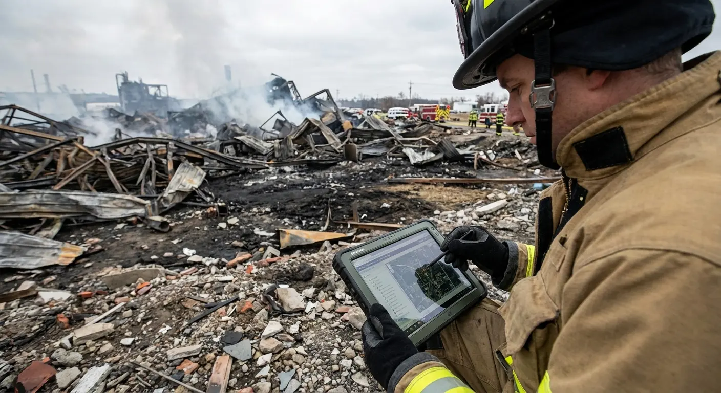
VCE investigations generate substantial data — damage measurements, fragment locations, witness statements, photographic documentation, and physical evidence across potentially large and complex scenes. Managing this volume of information systematically is where many investigations fail, not for lack of scene access or physical evidence, but because data cannot be correlated into a coherent reconstruction.
Blazestack's Fire Scene Data Collection module addresses this directly. The mobile platform allows investigators to document ignition sources, damage measurements, fragmentation positions, and evidence locations in real time on scene, with automatic photo logging that maintains organisation across hundreds of images captured across extended scenes. Scene data flows directly into NFPA 921-compliant origin and cause reports without manual reformatting. Chain of custody tracking ensures evidence collected from multiple locations maintains integrity through analysis and prosecution.
Investigators can test the platform with a 14-day free trial or schedule a demo to see the VCE documentation workflow in action.
Vapor cloud explosions challenge investigators because the primary evidence — the cloud itself — no longer exists on arrival. The investigation reconstructs an invisible, transient event from the damage it caused and the testimony of people who often did not understand what they were witnessing.
The confinement question shapes everything. Confined and unconfined VCEs produce different damage patterns, require different documentation approaches, and present different challenges in origin and cause determination. Most real-world events fall somewhere between the two, creating complex scenarios that demand careful analysis of hybrid damage signatures.
Physical evidence from VCE scenes tells a specific story when read correctly. Damage gradients map the cloud's extent. Fragmentation patterns reveal pressure dynamics. Witness marks preserve evidence of flame front passage. Surface effects distinguish deflagration from detonation. These indicators must be read together, not in isolation.
Ignition source determination requires working backward from damage patterns, understanding vapor behavior, and methodically eliminating possibilities through the structured process outlined above. The most damaged area is not where ignition occurred. Vapor density determines where explosive mixtures could form. Time governs how much accumulation was possible before ignition.
For a broader grounding in explosion investigation methodology, the fire and explosion investigation guide covers the full investigative framework within which VCE analysis sits.
The investigations that fail do not fail because of missing evidence or inadequate scene access. They fail because investigators could not manage the complexity, missed critical documentation windows, or could not correlate collected data into a coherent reconstruction. Measure everything. Document everything. Assume every conclusion will be challenged — because in VCE litigation, it will be.
Trusted by Public and Private Investigator Teams Everywhere
Whether you're a big state agency, a small local fire department or somewhere in between, Blazestack software (NFPA 921® & CJIS compliant) collects fire scene data and generates standardized origin and cause reports in a fraction of the time of other methods.
To learn more about Blazestack, give us a call at (866) 303-4344 or email us at support@blazestack.com
Get Your Free 14-Day Trial and Custom Price Quote Now
We'll let Blazestack do the talking. Try it out right now for free.
A member of our staff will be in touch shortly.